
Technical Information
Selecting a Soil Vapor Extraction Blower
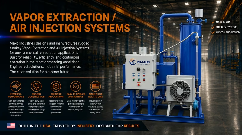
Published July 2026. Audience: remediation engineers, consultants, contractors, and system operators. This guide covers soil vapor extraction applications in the vadose zone; it is not a multi-phase liquid recovery design guide.
Educational use only. Site-specific design must be completed or reviewed by qualified professionals and must satisfy applicable permits, codes, manufacturer requirements, and health and safety plans.
Selection at a Glance
Start with the System, Not the Blower Catalog
Soil vapor extraction applies a vacuum to the unsaturated zone to induce controlled airflow and recover volatile contaminants for aboveground treatment. The blower is only one part of a connected hydraulic and treatment system.[1,2]
Five Decisions That Drive Selection
- Design airflow: total expected flow across the active well field.
- Required suction: subsurface response plus losses through wells, piping, separators, filters, and treatment.
- Gas condition: temperature, moisture, particulates, condensate potential, and chemical compatibility.
- Operating envelope: startup, normal operation, optimization, and late-stage lower-flow conditions.
- Controls and constraints: turndown, noise, electrical service, emissions control, and maintenance access.
Recommended Workflow
| Step | Output |
|---|---|
| 1. Characterize | Contaminant, geology, moisture, groundwater position, utilities, and discharge constraints. |
| 2. Pilot test | Measured flow-vacuum behavior, well response, vapor chemistry, temperature, and moisture loading. |
| 3. Build system curve | System resistance over the expected flow range, including aboveground equipment. |
| 4. Compare technologies | Manufacturer curves and allowable envelopes for candidate blower technologies. |
| 5. Validate | Motor load, treatment capacity, controls, sound, heat, materials, and upset response. |
Core Design Rule
The selected operating point is where the blower performance curve intersects the system curve. Do not specify flow and vacuum as unrelated maximum values; confirm that the blower can deliver the required flow at the required suction under the same stated inlet conditions.[2]
Why Oversizing Is Not a Harmless Default
A larger unit can increase capital cost, energy use, noise, heat, control complexity, and the risk of operating outside a stable or efficient range. It can also overload moisture-control or vapor-treatment components. A modest, documented allowance is useful; an arbitrary margin is not a substitute for pilot data and a system curve.
Define the Operating Point
Translate Field Response into Flow and Suction Requirements
The blower must overcome every pressure loss between the formation and the final discharge while delivering the airflow needed to create the intended subsurface capture and mass-removal response.
1. Use Pilot Testing to Anchor the Design
A step test at one or more extraction locations should record stabilized wellhead vacuum, airflow, observation-point vacuum response, vapor concentration, temperature, and moisture behavior at several operating settings. USACE guidance emphasizes using pilot-test data to develop the system response and to support blower sizing.[2]
| Measure | Why It Matters | Watch For |
|---|---|---|
| Airflow | Defines the recovered gas volume at each test condition. | State whether flow is actual or standardized and record temperature and pressure basis. |
| Wellhead vacuum | Shows the suction needed at the extraction point. | Gauge location, pulsing, restrictions, and water accumulation. |
| Vacuum response | Supports radius-of-influence and capture interpretation. | Prefer pressure response plus airflow evidence; one pressure reading is not a complete capture demonstration. |
| Vapor chemistry | Drives materials, treatment selection, permit evaluation, and mass-rate estimates. | Concentration can change substantially during startup and optimization. |
| Moisture / condensate | Determines separation, drainage, and blower protection needs. | Seasonal change, high water table, entrainment, and cooling in the piping. |
2. Account for the Complete Pressure Path
The pressure path includes formation and well losses, conveyance losses through pipe, fittings, valves, and manifolds, pretreatment losses through separators, filters, and heat exchangers, and vapor-control losses through carbon or oxidation equipment.
3. Plot More Than One Operating Condition
Evaluate startup, expected normal operation, a high-resistance condition such as a loaded filter or carbon bed, and a late-stage or reduced-well condition. Confirm each point against the candidate blower curve, motor rating, permissible temperature, and manufacturer operating limits.
Compare Blower Technologies
Match the Machine to the Required Operating Envelope
FRTR identifies three common categories for SVE: positive-displacement blowers, centrifugal or regenerative blowers, and liquid-ring pumps. Their practical fit depends on the required vacuum-flow combination and gas-handling conditions.[1]
| Type | Typical Fit | Strengths | Selection Cautions |
|---|---|---|---|
| Regenerative / centrifugal | Higher-permeability formations; comparatively higher flow at lower vacuum. | Compact and relatively simple; useful where the system curve is dominated by airflow rather than deep vacuum. | Capacity can change markedly with suction; confirm stable operating range, inlet temperature, turndown, and relief/bypass needs. |
| Positive displacement - rotary lobe | Moderate- to lower-permeability applications needing more consistent flow at higher vacuum. | Broad useful pressure capability; flow is comparatively less sensitive to pressure change. | Noise, pulsation, discharge temperature, overpressure protection, clearances, filtration, and lubrication configuration. |
| Liquid ring vacuum pump | High-vacuum or wet service; may be considered where liquids are present or for multi-phase applications. | Can tolerate wet gas and some liquid carryover better than dry machines. | Seal-liquid system, water quality and disposal, corrosion, freezing, utilities, heat rejection, and reduced efficiency. |
| Other vacuum technologies | Specialized duty where chemistry, vacuum, cleanliness, or footprint drives the decision. | May solve a defined constraint when standard blower types do not. | Require application-specific manufacturer review; do not generalize performance from a different gas or vacuum basis. |
Use Manufacturer Curves Correctly
Compare curves at the expected inlet pressure, gas temperature, gas composition, humidity, and electrical frequency. Confirm whether published capacity is actual inlet flow or standard flow. Obtain correction methods and allowable limits directly from the manufacturer for the proposed model.
Evaluate the Full Duty Cycle
| Condition | Evaluation |
|---|---|
| Startup | Potentially high vapor concentration, variable moisture, and rapidly changing flow. |
| Normal operation | The primary design point and expected energy-use basis. |
| Optimization | Individual wells throttled, pulsed, cycled, or taken offline. |
| Late stage | Lower mass loading and possibly a different active well network. |
Verify the Process Train
Protect the Blower - and the Equipment Downstream
SVE systems commonly include a moisture separator and particulate filter before the blower, followed by vapor treatment selected for the contaminant, concentration, and applicable discharge requirements.[1]
| Item | Design Question | Why It Changes Blower Selection |
|---|---|---|
| Air/water separator | Expected condensate and entrained-liquid load; high-level detection and drainage. | Adds pressure loss and upset controls; liquid carryover can damage dry blowers. |
| Particulate filtration | Expected particle size/loading and clean/dirty pressure drop. | A dirty filter shifts the operating point and may increase suction and temperature. |
| Temperature management | Compression heat, upstream heat, cooling, or dilution requirements. | Clearances, elastomers, bearings, motor load, and downstream media can be temperature-limited. |
| Vapor-phase carbon | Concentration, humidity, flow, changeout strategy, and allowable bed pressure drop. | Treatment capacity and pressure drop can constrain maximum practical blower flow. |
| Thermal / catalytic oxidation | Concentration limits, dilution, residence conditions, and permitted emissions. | May require stable flow, pressure, temperature interlocks, and concentration safeguards. |
| Silencer / discharge | Sound limit, stack configuration, and discharge pressure. | Backpressure and sound attenuation become part of the system and motor-load check. |
Minimum Instrumentation and Protective Functions
- Blower inlet vacuum and discharge pressure.
- Total flow plus individual well flow, as appropriate.
- Inlet and discharge temperature.
- Separator level and automatic shutdown.
- Filter differential pressure.
- Motor current or power and overload protection.
- Treatment-train temperature and differential pressure.
- Vapor sampling ports before and after treatment.
Hazard Review
Before startup, evaluate flammability, toxicity, oxygen-deficient or enriched conditions, static control, area electrical classification, hot surfaces, rotating equipment, condensate handling, and off-gas treatment upset modes. Establish alarm and shutdown setpoints through the project design and health and safety process.
Materials Compatibility
Review wetted and exposed materials against the expected vapor and condensate composition. Include housings, coatings, seals, gaskets, flexible connectors, valves, instruments, drain components, and treatment media - not only the blower casing.
Procurement Worksheet
Put the Design Basis on One Page
Complete this schedule before requesting final equipment selection. Attach pilot-test results, the system curve, candidate blower curves, and the pressure-drop basis.
| Input | Project Value to Document |
|---|---|
| Project / site | Project name and site location. |
| Design basis date / revision | Current design-basis date and revision. |
| Required airflow | Normal, minimum, maximum, and actual/standard basis. |
| Required inlet suction | Normal, maximum, and units. |
| Discharge pressure | Normal, maximum, and units. |
| Gas temperature | Normal/max inlet temperature and ambient range. |
| Gas composition | Contaminants and expected concentration range. |
| Moisture / liquids | Relative humidity and condensate/carryover condition. |
| Particulates | Expected loading and pretreatment. |
| Operating schedule | Hours/day and continuous, intermittent, or pulsed operation. |
| Control range | Required turndown and control method. |
| Electrical | Voltage, phase, and frequency. |
| Area / safety | Classification, flammability, toxicity, and special requirements. |
| Environment | Indoor/outdoor, altitude, weather, corrosion, and freeze protection. |
| Noise criterion | Limit at the applicable location/distance. |
| Treatment constraints | Maximum flow, temperature, pressure drop, and concentration. |
Required Vendor Submittal
Request the performance curve with the selected point and full operating range; power and motor load; inlet and discharge temperatures; noise data; materials; dimensions and weight; utility requirements; control and protection requirements; maintenance intervals; and explicit deviations from the specification.
Final Review
Confirm the Selection Before Purchase and Again at Startup
Design Review Checklist
- Pilot data represent the expected geology and well-field configuration.
- System curve includes clean and credible loaded/fouled conditions.
- Candidate curve shows the required point within the allowable operating range.
- Motor load, discharge temperature, and materials are acceptable.
- Moisture, particulates, and condensate are controlled.
- Treatment and permit constraints accommodate the complete flow range.
- Controls, alarms, shutdowns, relief, and bypass provisions are defined.
- Noise, power, footprint, lifting, drainage, and service access are resolved.
Startup Verification
- Verify rotation, alignment, lubrication, guards, flexible connectors, and valve lineup.
- Prove separator high-level, temperature, pressure, motor, and treatment interlocks.
- Start against the manufacturer-approved valve and control configuration.
- Record flow, suction, discharge pressure, temperature, motor load, and treatment differential pressure.
- Compare the measured operating point with predicted system and blower curves.
- Balance wells methodically and document final settings.
- Establish baseline vibration, sound, temperature, and differential-pressure readings.
- Train operators and issue approved operating, maintenance, and sampling procedures.
When to Revisit the Selection
Re-evaluate the operating point when the active well field changes, groundwater or moisture conditions shift, treatment media or equipment changes, pressure drop trends upward, the unit remains heavily throttled, or field performance no longer matches the design basis.
References
[1] Federal Remediation Technologies Roundtable (FRTR). Technology Screening Matrix: Soil Vapor Extraction. Accessed July 28, 2026.
FRTR Soil Vapor Extraction Technology Screening Matrix
[2] U.S. Army Corps of Engineers. Engineering Manual EM 1110-1-4001: Soil Vapor Extraction and Bioventing. June 3, 2002.
[3] U.S. Army Corps of Engineers. Engineering Manual EM 1110-1-4010: Multi-Phase Extraction. June 1, 1999. Used for compressible-flow and system-curve context.
[4] U.S. Environmental Protection Agency. Soil Vapor Extraction (SVE) Technology: Engineering Issue Paper. EPA/600/R-18/053, 2018.
EPA SVE Engineering Issue Paper
Document control: Technical Guide 01 | July 2026 | Version 1.0